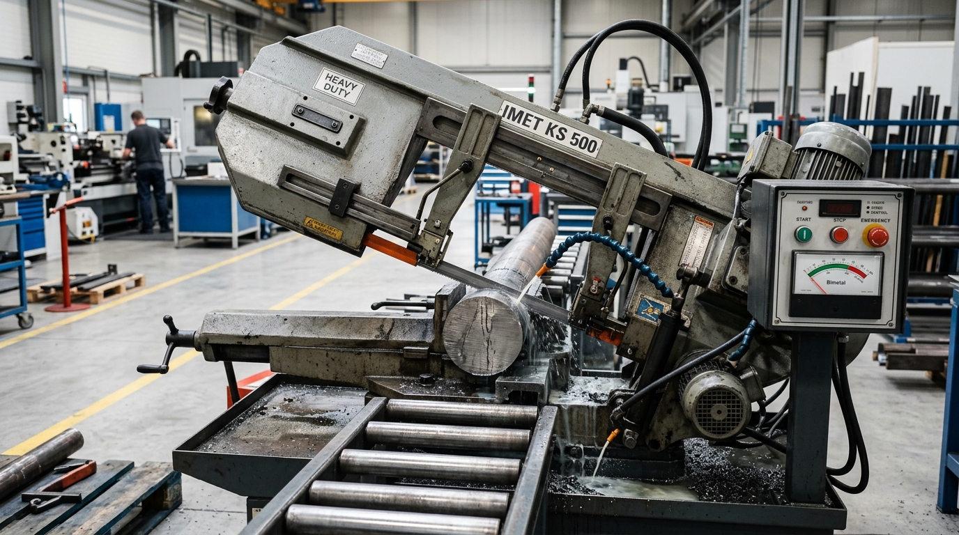
Fundamentals of Industrial Horizontal Metal Band Sawing
Horizontal metal band sawing represents the essential primary operation in metal fabrication, machine building, and raw material preparation. While often regarded as a simple roughing process, precision sawing directly impacts subsequent machining operations. Excessive cut taper, rough surface finish, or work-hardened cut faces will dramatically increase cycle times and tool wear on downstream CNC machining centers and lathes.
Achieving high metal removal rates while maximizing bi-metal blade life requires a rigorous understanding of blade tooth geometry, beam rigidity, cutting speed (surface meters per minute), hydraulic downfeed force, and fluid lubrication dynamics.
1. Bi-Metal & Carbide Blade Selection Rules
Modern band saw blades primarily utilize M42 high-speed steel (8% cobalt) or M51 powder metal tooth tips electron-beam welded to a high-strength spring alloy backing strip. For high-nickel alloys and case-hardened steels, carbide-tipped (TCT) blades provide superior thermal endurance.
Variable Tooth Pitch (TPI) Selection Table
Using a variable pitch blade (e.g., 3/4 TPI or 4/6 TPI) disrupts harmonic resonance during cutting, dampening vibration and eliminating chatter marks on the cut face.
| Workpiece Cross-Section / Diameter | Recommended Pitch (TPI) | Tooth Geometry | Typical Applications |
|---|---|---|---|
| Solid Rounds Ø150 mm – Ø400 mm | 2/3 TPI or 1.4/2.0 TPI | Positive Rake (10°–15°) | Carbon steel billets, forged bars, tool steels |
| Solid Rounds Ø50 mm – Ø150 mm | 3/4 TPI or 4/6 TPI | Positive Rake (6°–10°) | 4140, 4340 alloy shafts, 304/316 stainless bars |
| Thick Wall Tubes (Wall 10 – 30 mm) | 4/6 TPI or 5/8 TPI | Neutral / Light Positive (0°–5°) | Hydraulic cylinders, structural heavy pipe |
| Thin Wall Tubes & Profiles (< 6 mm) | 8/12 TPI or 10/14 TPI | Neutral Rake (0°) | Box tubing, angle iron, structural channel |
| Bundled Solid Small Bars | 5/8 TPI (Vari-Tooth) | Reinforced Back Tooth | Multi-bar production bundle sawing |
Golden Rule of Engagement: Ensure a minimum of 3 teeth are engaged in the cut at all times to prevent tooth stripping, and no more than 24 teeth are engaged simultaneously to avoid chip gullet clogging.
2. Cutting Speed (m/min) and Downfeed Dynamics
Cutting speed (Vc) in meters per minute must be precisely matched to the machinability index of the material. Excessive speed generates catastrophic friction heat at the tooth tip, resulting in micro-chipping; insufficient speed leads to tooth rubbing, burnishing, and work-hardening.
Material Cutting Speed & Feed Guidelines
- Mild & Low Carbon Steels (AISI 1018, 1020, S275, S355):
- Cutting Speed: 65 – 85 m/min
- Downfeed Pressure: Medium-High (Chip curl should be thick and loosely coiled)
- Medium Carbon & Alloy Steels (AISI 1045, 4140, 4340, 42CrMo4):
- Cutting Speed: 45 – 60 m/min
- Downfeed Pressure: High (Firm hydraulic resistance with consistent needle valve feed)
- Austenitic Stainless Steels (AISI 304, 316, 316L):
- Cutting Speed: 25 – 35 m/min
- Downfeed Pressure: High continuous feed (Never let teeth dwell or rub to avoid rapid work hardening)
- Tool Steels & Die Steels (D2, H13, P20, SKD11):
- Cutting Speed: 20 – 35 m/min
- Downfeed Pressure: Controlled moderate feed with high-pressure flood coolant
- Aluminum Alloys & Brass (6061-T6, 7075, CuZn39Pb3):
- Cutting Speed: 80 – 120 m/min (or maximum inverter speed)
- Downfeed Pressure: Fast rapid feed with generous chip evacuation
3. Blade Tensioning & Guide Roller Alignment
Blade tension is the cornerstone of straight cutting. A horizontal band saw operating with inadequate tension will experience lateral blade deflection (bowing or belly cutting), producing out-of-square cuts.
- Optimal Blade Tension: Maintain 28,000 to 32,000 PSI (190 to 220 MPa) across the blade body using a calibrated hydraulic or mechanical tension meter.
- Carbide Guide Block Clearance: The tungsten carbide side guide blocks must be set with 0.03 mm to 0.05 mm total clearance against the blade sides. Guide blocks must never pinch the blade body.
- Guide Arm Spacing: Always position the movable guide arm as close to the workpiece as possible (maximum 15–20 mm gap) to minimize unsupported blade span and maximize beam stiffness.
4. Coolant Concentration & Chip Inspection
The metal chips produced during sawing provide immediate diagnostic feedback regarding feed pressure and cutting conditions:
- Thin, powdery or burnt brown chips: Feed pressure is too low; teeth are rubbing instead of shearing. Increase downfeed pressure immediately.
- Thick, tightly curled, blue-colored chips: Cutting speed or feed rate is excessive. Decrease blade speed or reduce downfeed.
- Clean, silvery, loosely curled spiral chips: Ideal cutting state. Optimum balance between tooth load and blade life.
Use a high-quality water-soluble semi-synthetic or synthetic cutting fluid at a 7% to 10% concentration (Brix scale). Ensure dual flood nozzles direct fluid directly into the cut kerf on both sides of the carbide guide blocks to wash away chips and lubricate tooth flanks.
5. Daily & Weekly Preventive Maintenance Checklist
To maintain sub-0.2 mm perpendicularity across a 400 mm cut length:
- Daily: Clear chips from the drive wheel housing and wire chip brush. Adjust the chip brush so its bristles penetrate 1 mm into the tooth gullet.
- Daily: Inspect hydraulic oil level and verify needle valve downfeed smoothness across the entire bow stroke.
- Weekly: Check carbide guide inserts for chipped edges or uneven wear. Rotate or lap guide pads as necessary.
- Monthly: Check drive gearbox oil level (ISO VG 320 synthetic gear oil) and verify guide arm dovetail gib tightness.