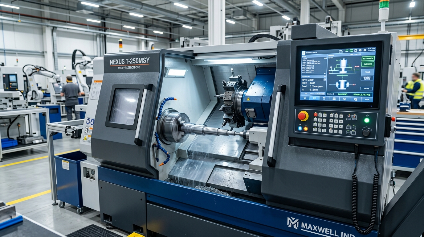
Advanced Engineering Principles in CNC Lathe Turning
CNC turning represents one of the most critical foundational processes in mechanical engineering. Modern CNC lathes must handle diverse machining requirements ranging from heavy roughing of forged billets to sub-micron finishing of hardened alloy shafts and thin-walled bearing flanges.
Achieving superior cylindricity, concentricity under 0.005 mm, and Ra 0.4 surface finishes requires rigorous optimization of chucking pressure, tool nose radius compensation, insert geometry, multi-pass threading parameters, and tailstock quill thrust.
1. Machine Bed Construction: Flat Bed vs Slant Bed Dynamics
Heavy-duty CNC turning machines feature high-grade Meehanite castings with induction-hardened guideways:
- Induction Hardened & Precision Ground Guideways: Guideway surfaces heat-treated to HRC 50–55 with a hardening depth of 2.5 to 3.5 mm provide decades of wear resistance against abrasive cast iron dust and high cutting forces.
- Vibration Absorption: The wide span between longitudinal Z-axis ways lowers the machine's center of gravity, minimizing carriage pitching moments during high-depth roughing passes (ap >= 4.0 mm).
- Headstock Spindle Bearings: Precision high-load double-row cylindrical roller bearings paired with duplex angular contact thrust bearings maintain radial runout under 0.003 mm at the spindle nose (A2-8).
2. Hydraulic Power Chuck Clamping Force & Soft Jaw Boring
Improper workpiece clamping is the leading cause of workpiece deformation on thin flanges or dangerous part slippage during high-torque turning.
Centrifugal Clamping Force Loss
As spindle speed increases, centrifugal force acting on the chuck master jaws and top jaws counteracts internal hydraulic cylinder force. At 2,500 RPM, a 10" hydraulic 3-jaw chuck can lose up to 40% to 50% of its initial static clamping force.
Soft Jaw Machining Rules:
- Bore Under Operating Pressure: Always bore soft jaws with the hydraulic cylinder clamped onto a dedicated boring ring or spider at the exact hydraulic pressure (e.g., 2.0 to 2.5 MPa) intended for production.
- True Concentricity: Machine jaw clamping diameters to exact workpiece nominal dimension +0.05 mm to maximize contact surface area and prevent 3-point out-of-round deformation.
- Internal Gripping Serrations: For roughing forgings, machine small serrations (0.2 mm pitch) into the jaw face to dramatically increase grip coefficient.
3. Hard Turning (HRC 45–62) vs Cylindrical Grinding
With high-rigidity CNC lathes, hard turning using Polycrystalline Cubic Boron Nitride (PCBN) or mixed ceramic inserts can completely replace cylindrical grinding for shafts, gears, and bearing races.
| Machining Attribute | Hard Turning (CNC Lathe + CBN) | Traditional Cylindrical Grinding |
|---|---|---|
| Cycle Time | 2 to 3 times faster | Baseline |
| Flexibility | Multiple diameters, contours, faces in 1 setup | Requires dedicated dressing and wheels |
| Surface Roughness | Ra 0.2 - 0.4 μm (Ground-equivalent) | Ra 0.1 - 0.3 μm |
| Environmental Impact | Dry cutting / minimal MQL | Heavy grinding sludge and coolant disposal |
| Capital Investment | Utilizes existing CNC turning center | Requires dedicated grinding machine |
Key Parameters for Hard Turning:
- Insert Edge Preparation: Always specify a honed (25 μm) or chamfered (T-land 0.1 mm x 20°) cutting edge. Sharp razor edges will chip instantly on hardened steel.
- Cutting Speed: 100 - 160 m/min.
- Feed Rate: 0.08 - 0.15 mm/rev.
- Depth of Cut: 0.1 - 0.3 mm (Must exceed insert edge hone radius to ensure clean chip shear rather than burnishing).
4. CNC Threading Optimization: G76 Compound Infeed vs G92
Threading requires balancing cutting forces on both insert cutting edges:
- Radial Infeed (G92 / Direct Plunge): Tool feeds perpendicular to the workpiece axis. Both flanks cut simultaneously, creating V-shaped chips that can easily wedge, cause chatter, and tear thread flanks.
- Modified Flank Infeed (G76 Multiple Repetitive Cycle): The tool feeds at an infeed angle of 29° (for 60° ISO metric threads). Cutting occurs primarily on the leading edge, allowing chips to curl freely and leaving a pristine finish on the trailing flank.
Recommended Threading Passes for ISO Metric M30x2.0:
- Pass 1: ap = 0.40 mm
- Pass 2: ap = 0.30 mm
- Pass 3: ap = 0.22 mm
- Pass 4: ap = 0.15 mm
- Pass 5: ap = 0.10 mm
- Pass 6: ap = 0.05 mm (Spring pass / clean pass with zero nominal infeed)
5. Long Shaft Turning: Tailstock & Steady Rest Setup
When turning shafts where length exceeds 4 times diameter (L/D > 4), workpiece deflection under radial cutting force causes dimensional barreling (parts larger in the center):
- Hydraulic Tailstock Quill Pressure: Adjust quill thrust between 3.0 to 8.0 kN depending on shaft diameter. Excessive thrust bows the shaft; insufficient thrust causes center point slippage.
- Live Center Runout: Verify live center point runout is under 0.005 mm TIR.
- Follow Rest & Steady Rest: For L/D > 10, utilize a 3-point roller steady rest or hydraulic programmable steady rest clamped at the shaft mid-point. Always skim a true round journal before positioning steady rest roller bearings.