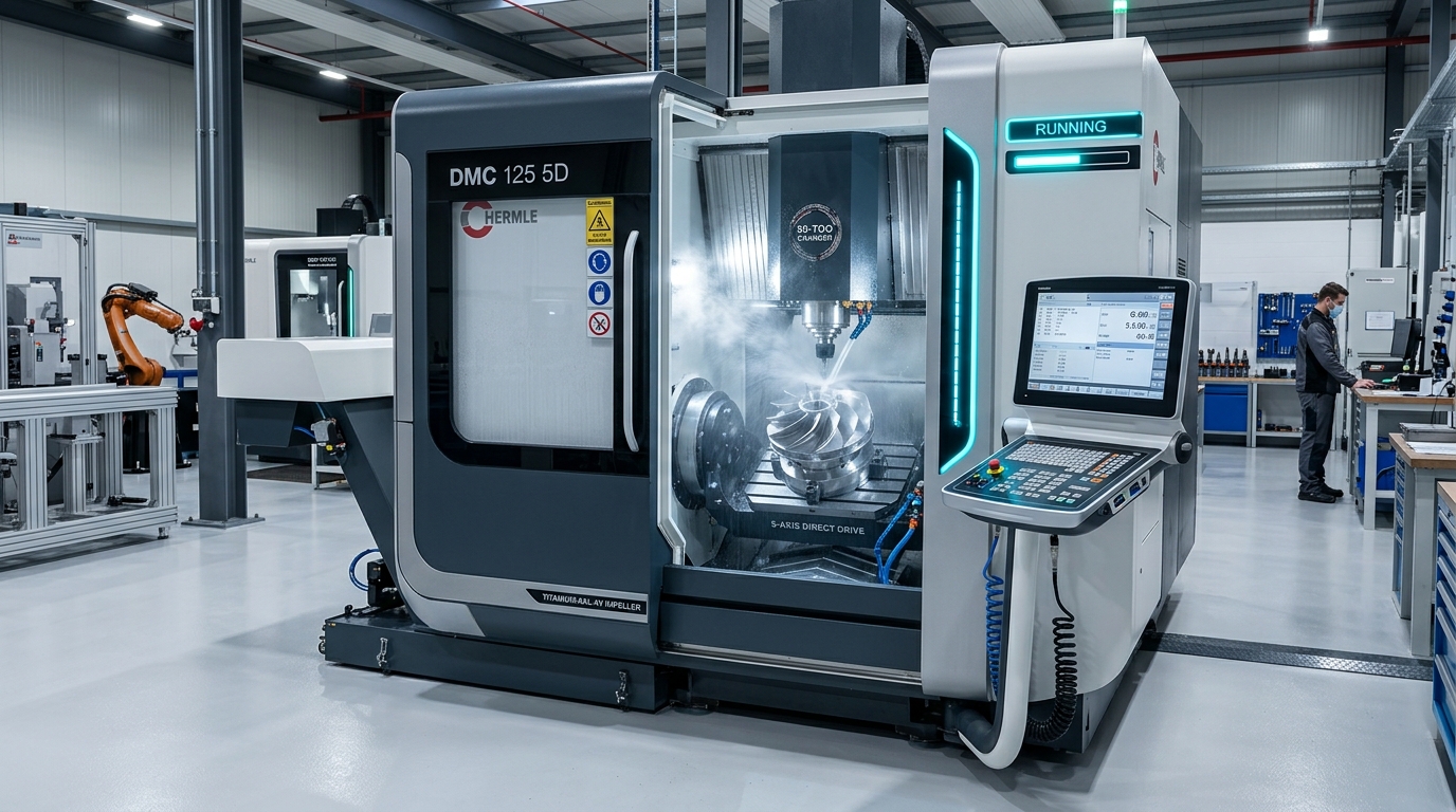
Engineering Foundations of Vertical CNC Machining Centers
In contemporary batch production and precision mold manufacturing, vertical machining centers (VMCs) serve as the backbone of shop floor productivity. However, achieving micron-level tolerances (under ±0.005 mm) during high-speed cutting requires much more than simply running aggressive spindle speeds and feed rates.
Maximizing metal removal rates (MRR) without sacrificing tool life or surface roughness depends on the holistic interplay of machine structure rigidity, thermal stabilization, CNC look-ahead algorithms, dynamic tool balancing, and modern milling path strategies.
1. Structural Rigidity: Cast Iron Geometry & Guideway Dynamics
The machine's structural loop dictates its natural resonant frequency. When cutting forces match the machine's resonant frequency, severe harmonic chatter occurs, destroying carbide cutting edges and ruining workpiece surface finish.
- Meehanite FC300 Heavy Cast Frame: High-density gray cast iron possesses up to 10 times higher internal vibration damping capacity compared to welded steel structures. Dense triangular internal ribbing within the column and base effectively dissipates torsional and bending loads during heavy face milling.
- Roller vs Ball Linear Guideways: High-precision roller linear guideways provide line contact rather than point contact. This yields up to 2.5 times higher load rigidity and superior damping under heavy interrupted cutting loads.
- Preloaded C3 Double-Nut Ballscrews: Direct-coupled digital servo motors driving pretensioned ballscrews eliminate axial play and minimize thermal elongation effects during high-speed rapid traverses (36 m/min).
2. Spindle Thermal Growth & Chiller Management
Spindle thermal growth along the Z-axis is the single largest contributor to dimensional drift in vertical machining centers over an 8-hour production shift. High-speed rotation of spindle bearings and motor windings generates internal heat:
Even a temperature rise of 4°C across a 400 mm spindle length produces more than 0.015 mm of Z-axis thermal drift, sufficient to fail tight aerospace or mold cavity tolerances.
Thermal Stabilization Best Practices:
- Closed-Loop Spindle Oil Chillers: Always operate a dedicated refrigerated oil cooler that circulates sub-cooled fluid through the spindle housing jacket, actively maintaining spindle bearing temperature within ±0.5°C of ambient factory temperature.
- Warm-Up Cycle: Run a 15-minute stepped spindle warm-up routine (2,000 → 5,000 → 8,000 RPM) each morning prior to setting work coordinate datums or cutting tight-tolerance features.
- Internal Optical Glass Scales: For sub-micron positioning, optical linear scales provide direct axis feedback, bypassing ballscrew thermal expansion entirely.
3. High-Feed Milling (HFM) vs Trochoidal Toolpath Strategies
Traditional heavy-depth milling toolpaths subject cutters to extreme engagement angle spikes during corner transitions, leading to tool deflection and chatter. Modern CAM programming utilizes specialized high-efficiency strategies:
| Milling Strategy | Radial Depth (ae) | Axial Depth (ap) | Chip Thinning Effect | Primary Application |
|---|---|---|---|---|
| High-Feed Milling (HFM) | 60% – 80% D | 0.5 – 1.5 mm | Very High (small lead angle 10°-15°) | Deep cavity roughing, high-hardness die steels |
| Trochoidal / Dynamic Milling | 8% – 15% D | Up to 2.5 x D | High (Radial chip thinning) | Deep pockets, titanium, stainless steel slots |
| Conventional Face Milling | 65% – 75% D | 2.0 – 4.0 mm | Standard | Squaring stock, facing plate surfaces |
Advantages of Dynamic / Trochoidal Milling:
- Constant cutter engagement angle (under 50°) eliminates shock loading on spindle bearings.
- Utilizes full flute length (ap), distributing wear evenly along the carbide tool instead of concentrating wear at the tip.
- Enables cutting speed (Vc) increases of 50% to 100% with feed rates exceeding 6,000 mm/min.
4. Toolholding Systems: Runout & Dynamic Balance
At spindle speeds above 8,000 RPM, centrifugal force and centrifugal toolholder expansion significantly amplify tool runout. Tool runout exceeding 0.005 mm TIR (Total Indicated Runout) reduces carbide end mill service life by up to 50%.
- Hydraulic Chucks & Shrink-Fit Holders: Deliver runout accuracy under 0.003 mm at 3xD overhang, providing exceptional clamping force and concentricity for high-speed finishing.
- Dual Contact (BBT / Face-Taper Spindle Interface): Simultaneous taper and face contact eliminates spindle taper expansion under centrifugal force, enhancing axial Z-axis repeatability and lateral stiffness by over 40%.
- Dynamic Balancing: Ensure all tool assemblies are balanced to G2.5 standard at 15,000 RPM to safeguard spindle bearings and prevent harmonic surface waviness.
5. Standard 10-Point Pre-Operation Inspection Checklist
Perform this mandatory 5-minute pre-shift inspection before commencing batch production:
- Verify automatic central lubrication pump pressure (minimum 1.5 MPa) and oil reservoir level.
- Check spindle oil chiller temperature display (target: ambient ±0.5°C).
- Inspect compressed air regulator pressure (minimum 0.6 MPa clean dry air for tool unclamp and spindle air purge).
- Verify coolant level and test water-soluble fluid concentration with an optical refractometer (8% to 10% Brix).
- Clean spindle taper bore with a lint-free wiper to remove stray chips or oil film.
- Inspect toolholder pull studs for wear, pitting, or burrs.
- Verify workpiece vise clamping pressure and torque wrench calibration.
- Perform tool length probe calibration check.
- Verify program zero datum (G54-G59) with a 3D edge finder or optical touch probe.
- Confirm enclosure door safety interlocks and emergency stop button operation.