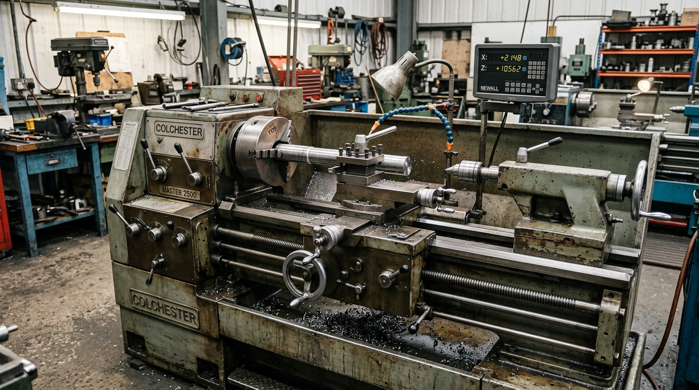
The Strategic Role of Universal Manual Lathes in Modern Toolrooms
Despite widespread automation, heavy-duty universal manual engine lathes remain irreplaceable assets in industrial maintenance facilities, repair stations, aerospace toolrooms, and prototyping workshops.
A skilled machinist equipped with a rigid manual lathe can turn one-off replacement shafts, re-thread damaged pump impellers, and bore custom large-diameter flanges in less time than it takes to program, simulate, fixture, and qualify a part on a CNC lathe.
Achieving toolroom-grade accuracy (concentricity and taper under 0.01 mm over 300 mm) requires proper mastery of gap bed bridge removal, universal gearbox threading charts, optical Digital Readout (DRO) techniques, and carriage alignment.
1. Removable Gap Bed (Bridge) Disassembly & Re-Pinning
The removable gap bed bridge allows turning large-diameter, short-length workpieces (such as large pump impellers, brake drums, boiler flanges, and flywheel rings) that exceed the standard swing over bed by 40% to 50%.
Safe Gap Removal & Installation Procedure:
- Disassembly:
- Clean all chips, grease, and grime from the gap mating joint.
- Unscrew the hex extraction nuts on the two hardened precision taper locating pins. Draw the taper pins out smoothly using an extraction slide hammer or nut puller.
- Remove the heavy socket head cap screws securing the gap piece to the main casting base.
- Carefully lift the gap piece straight upward using an overhead crane or hoist with soft nylon slings. Never pry the precision ground way surfaces with steel bars.
- Re-Installation & Alignment:
- Thoroughly de-burr and stone the mating joint faces with a fine India oilstone.
- Lower the gap piece into position and loosely install the main securing bolts.
- Clean and lightly oil the hardened taper locating pins; drive them firmly home with a brass drift punch to establish exact factory geometric location.
- Tighten main securing bolts in a cross pattern to factory torque specification (180 Nm).
- Sweep a 0.001 mm dial test indicator (DTI) mounted on the carriage across the gap joint. The step height transition must be under 0.005 mm with zero perceptible ridge.
2. Universal Quick-Change Threading Gearbox Operation
Modern universal manual lathes feature enclosed, oil-immersed quick-change gearboxes that cut a complete range of metric, Whitworth imperial inch, module, and diametral pitch (DP) threads without requiring manual change gear swapping on the quadrant bracket.
Threading Standards Comparison Table
| Thread Classification | Pitch Designation Range | Typical Industrial Usage | Gearbox Lever Engagement |
|---|---|---|---|
| ISO Metric | 0.50 mm – 120 mm | General machinery, bolts, tie rods | Position A-B-C / Leadscrew Active |
| Whitworth Imperial (UN / BSW) | 7/16 – 60 TPI | Oil & gas piping, hydraulic fittings | Position D-E-F / Leadscrew Active |
| Module (m) | 0.25 – 10 mm | Worm drives, gear racks, lead nuts | Module Selection Chart |
| Diametral Pitch (DP) | 8 – 120 DP | Heavy drive worms, winch mechanisms | DP Selection Chart |
Half-Nut Engagement Rules:
- Metric Threading with Metric Leadscrew: The thread chaser dial can be used to re-engage the half-nut at designated dial numbers for even pitch values.
- Odd / Special Imperial Threading: Keep the half-nut continuously engaged throughout the entire threading cycle. At the end of each cutting pass, rapidly withdraw the cross-slide, stop the spindle, and reverse spindle rotation back to the start point to ensure pitch synchronization.
3. Optical 3-Axis Digital Readout (DRO) Calibration & Tool Offsets
A precision 3-axis optical Digital Readout (DRO) with 1 μm resolution glass scales eliminates operator errors caused by manual vernier dial backlash:
- Diameter vs Radius Mode: Configure the X-axis DRO display to Diameter mode (2x scale reading) for direct workpiece diameter verification.
- Tool Library Memory: Modern DRO consoles support up to 200 stored tool offsets. Program offset positions for the roughing tool, finishing tool, parting blade, and internal boring bar on a quick-change 4-position tool post to eliminate manual re-touching between operations.
- Bolt Hole Circle (PCD) & Taper Calculation: Utilize the built-in DRO trigonometry functions to compute precise compound slide angles and hole drilling coordinates.
4. Headstock Spindle & Tailstock Alignment Checks
Over time, heavy turning operations or accidental chuck bumps can cause headstock spindle misalignment:
2-Collar Test for Lathe Alignment:
- Chuck a 50 mm diameter solid steel test bar (AISI 1045) extending 250 mm without tailstock support.
- Turn two identical test collars (Ø45 mm x 15 mm length) at the chuck end and at the unsupported outboard end using a sharp, fine-finishing insert (nose radius = 0.2 mm, depth of cut ap = 0.1 mm).
- Measure both turned collars with a calibrated 25–50 mm micrometer (0.001 mm vernier).
- If the diameter at the outboard collar is larger or smaller than the chuck collar by more than 0.008 mm, loosen the headstock hold-down bolts and adjust the lateral alignment jacking screws until both collars measure identical within 0.003 mm.
5. Lubrication Schedule for Manual Lathes
| Location | Lubricant Type | Frequency | Action |
|---|---|---|---|
| Bedway Slideways & Carriage | ISO VG 68 Way Oil (Anti-stick-slip) | Every Shift (Daily) | Pump manual carriage one-shot oiler 3 times |
| Headstock Gearbox | ISO VG 46 Anti-Wear Hydraulic / Machine Oil | Check Weekly / Change Annually | Maintain oil level in sight glass; drain and flush yearly |
| Apron & Threading Gearbox | ISO VG 46 / 68 Oil Bath | Check Monthly / Change Annually | Refill reservoir to center mark |
| Tailstock Quill & Leadscrew Bearings | High-Pressure Lithium Grease (NLGI 2) | Weekly | Inject grease via ball-check fittings |