Precision Toolroom Machining with Vertical Turret Milling Machines
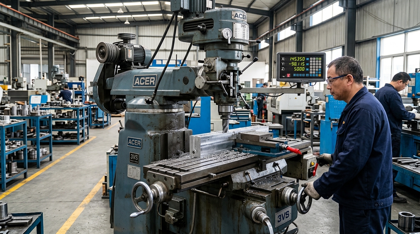
The vertical turret milling machine (often termed the knee-and-column toolroom mill) remains one of the most flexible machine tools ever created. Equipped with an articulating swivel head, chrome-hardened quill, 3-axis power feeds, and optical Digital Readouts (DRO), it performs complex angle milling, precision boring, pocketing, slotting, and drilling across individual components and tooling fixtures.
Achieving sub-0.01 mm squareness and eliminating chatter marks during face milling requires strict procedural discipline in head tramming, leadscrew split-nut backlash adjustment, Turcite-B slideway gib tuning, and cutting speed selection.
1. Milling Head Tramming (Squaring the Spindle to Table)
Whenever the milling head is tilted for angle milling or after heavy interrupted cutting, the spindle axis must be precisely trammed square to the longitudinal (X) and transverse (Y) axes of the table.
Twin-Indicator Tramming Procedure:
- Mount a rigid dual-indicator tramming fixture into the spindle collet (R8 or NT40) with a sweep radius of 150 mm (300 mm diameter span).
- Clean and stone the precision ground table surface.
- Lower the quill until both indicator needles contact the table face and preload each dial to mid-travel (e.g., 1.0 mm preload). Zero both dial faces.
- X-Axis (Side-to-Side Tramming):
- Read the difference between left and right indicators across the 300 mm span.
- Loosen the four head clamping nuts on the swivel flange.
- Adjust the worm gear tilting drive bolt until both indicators read identical (< 0.005 mm TIR over 300 mm). Torque nuts in a cross pattern to 75 Nm.
- Y-Axis (Nodding / Front-to-Back Tramming):
- Rotate the tramming fixture 90° so indicators align with the front and rear of the table.
- Loosen the ram knuckle locking bolts and adjust the nodding worm drive until front and rear readings match within 0.005 mm. Re-torque clamping bolts securely.
2. Eliminating Leadscrew Backlash: Split-Nut Adjustment
During conventional milling and especially climb milling (down milling), leadscrew backlash can cause the milling table to be aggressively pulled into the cutter, causing tool breakage or part gouging.
- Split Brass Leadscrew Nut: Precision milling tables feature an adjustable split bronze nut assembly under the saddle for both the X and Y axis leadscrews.
- Adjustment Procedure:
- Traverse the table to its center position where leadscrew wear is highest.
- Locate the backlash adjustment screw on the right side of the split nut housing underneath the saddle.
- Loosen the lock nut and carefully tighten the wedge adjustment screw until leadscrew backlash measured on the handwheel dial decreases to 0.05 mm – 0.08 mm (0.002" – 0.003").
- Traverse the table along its entire full stroke from left to right. The table must move smoothly with no tight binding at the stroke ends. Lock the adjustment lock nut securely.
3. Inverter Variable Speed Head vs Stepped Pulley Heads
Modern precision turret mills utilize electronic inverter-driven variable speed heads operating across 60 to 4,200 RPM:
| Feature | Electronic Inverter Drive (Yaskawa/Delta) | Traditional Mechanical Vari-Disc Belt Drive |
|---|---|---|
| Speed Adjustment | Digital dial knob / Potentiometer on pendant | Mechanical hand crank with split vari-discs |
| Mechanical Wear | Zero belt vari-disc wear; direct inverter modulation | Plastic bushings, keys, and split sheaves wear rapidly |
| Vibration & Noise | Ultra-quiet (< 68 dB), balanced high-torque motor | Mechanical rattle occurs as vari-disc bushings wear |
| Low-End Torque | High torque vector control down to 60 RPM | Requires manual back-gear engagement for low speeds |
| Spindle Tapping Mode | Instant electronic spindle reverse with foot switch | Relies on mechanical motor reversing switch |
4. Spindle Taper Care & Collet Chuck Systems
The spindle taper is the precision datum for all tooling:
- R8 vs NT40 Taper:
- R8 Spindle: Ideal for toolrooms, collets up to Ø20 mm, high accessibility for delicate prototype milling.
- NT40 Taper: 300% greater contact surface area, rigid flange drive keys, superior for heavy face milling cutters (>= Ø80 mm) and roughing passes.
- Air Power Drawbar: An automatic pneumatic drawbar eliminates manual hammer-wrenching on the drawbar, protecting spindle precision angular contact bearings from axial impact shock and changing tools in under 3 seconds.
5. Machine Vise Clamping & Squaring Best Practices
The precision milling vise is the primary workholding interface:
- Squaring the Fixed Vise Jaw: Always indicate the fixed (rear) jaw of the vise with a 0.001 mm dial test indicator while traversing the table along the X-axis. Never indicate the movable front jaw. Align fixed jaw squareness under 0.005 mm across a 150 mm width.
- Workpiece Parallels & Clamping: Always support workpieces on precision ground matched parallel pairs. After clamping the vise handle firmly, lightly tap the workpiece down with a dead-blow brass or polyurethane mallet until both parallels are firmly locked and cannot be wiggled by hand.
- Climb Milling Caution: On manual milling machines without zero-backlash ballscrews, always use conventional milling (up milling) for heavy roughing passes to prevent the cutter from grabbing and pulling the table into the cut. Use climb milling exclusively for light finish passes (radial depth ae <= 0.2 mm).